
You bought the WiFi 6 router. You placed the mesh nodes exactly where the app told you to. And the pool house still buffers every evening at 8 p.m.
Nothing on Amazon will fix this. The router is not the problem, the internet plan is not the problem, and adding a fourth mesh node will not be the problem either. The walls, windows and floors of your home are doing the blocking, quietly, every minute, by the laws of physics.
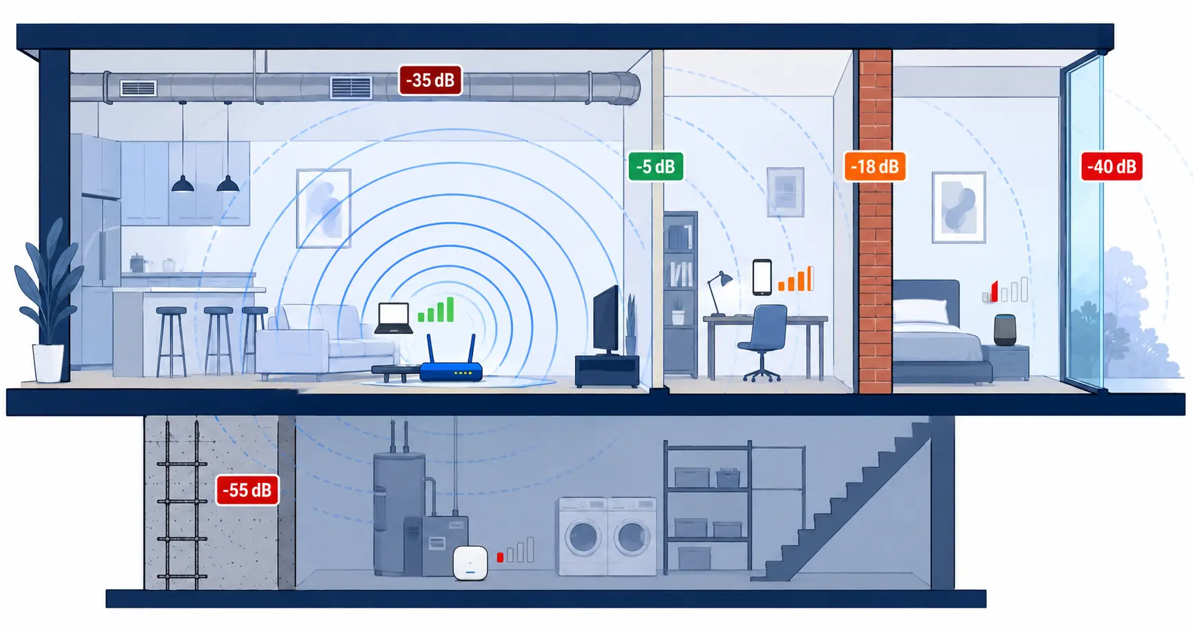
Reinforced concrete walls can reduce a WiFi signal by 31 dB at 2.4 GHz and 55 dB at 5 GHz, which is enough to push a strong signal deep into the unusable range. This article shows exactly how much signal each common construction material steals, why higher frequencies make the problem worse instead of better, and why no consumer fix can claw the loss back. Before walking through each material, the number that drives all of this needs a moment of explanation.
What WiFi Signal Strength Actually Means
WiFi signal strength is measured in dBm, where -30 dBm is excellent and -80 dBm is unusable. The scale is logarithmic, so every 3 dB lost is roughly half the signal power, and every 10 dB lost is a tenfold drop. A reading of -50 dBm supports 4K streaming without a hiccup, while -70 dBm starts to break video calls and smart-home reconnects. Here is what the numbers feel like in daily use:
| Signal level | Throughput (typical) | Latency / packet loss | Real-world experience |
|---|---|---|---|
| -30 to -50 dBm | 400-900 Mbit/s | 1-5 ms, 0% loss | 4K streaming, video calls, smart home all stable in parallel |
| -50 to -67 dBm | 100-300 Mbit/s | 5-20 ms, <0.1% loss | Streaming and calls reliable, occasional smart-home reconnects |
| -67 to -75 dBm | 20-80 Mbit/s | 20-80 ms, 0.5-2% loss | Video calls drop to 360p, 4K streams buffer, smart devices stutter |
| -75 to -85 dBm | 1-15 Mbit/s | 100-500 ms, 2-5% loss | Constant buffering, calls cut out, slow page loads |
| Below -85 dBm | none | full disconnect | “No signal” in practice |
Every wall, window and floor between the router and the device subtracts dB from that number, and the subtractions stack. Industry calls this signal attenuation (loss of signal strength through a material), and a single luxury home can stack five or six attenuation events between a router and a far bedroom. Each additional wall between router and device subtracts measurable dB from the signal, and the losses compound across the whole path. That sets up the practical question: how much does each material in a high-end home actually cost you?
The Six Materials That Eat Your WiFi – With Real dB Numbers
Reinforced concrete is the heaviest hitter, low-E glass is the silent surprise, and metal is the worst of all because it does not just absorb, it scatters. Field-measured attenuation values vary by source and by test method, but the ranges below reflect what enterprise installers see across thousands of luxury properties. The summary table comes first; the per-material details follow. Published source data behind these numbers comes from the NIST Technical Report on indoor RF propagation and the Cisco Mesh Deployment Guide.
Comparison Table: Signal Loss at a Glance
| Material | 2.4 GHz loss | 5 GHz loss | Where it shows up | Real-world impact (from -50 dBm baseline) |
|---|---|---|---|---|
| Drywall (stud wall) | 1-4 dB | 3-6 dB | Interior walls between rooms | -56 dBm: full speed, still excellent |
| Solid wood | 3-4 dB | 6-8 dB | Doors, exposed beams, paneling | -58 dBm: still excellent, no slowdown |
| Clear glass | 2-3 dB | 4-6 dB | Older single-pane windows | -56 dBm: full speed, no impact |
| Brick | 6-10 dB | 15-20 dB | Exterior walls, chimneys, facades | -70 dBm: video calls degrade, 4K buffers |
| Low-E glass | 10-25 dB | 20-40 dB | Modern energy-efficient windows | -90 dBm: unusable, calls drop |
| Metal (steel/iron) | 25-35 dB | 35+ dB | Beams, HVAC ducts, appliances | -85 dBm or worse: disconnect |
| Concrete (8 inch) | 29 dB | 48 dB | Foundations, basement walls | -98 dBm: no signal |
| Reinforced concrete | 31 dB | 55 dB | Modern poured walls, party walls | -105 dBm: completely blocked |
A single reinforced concrete wall can attenuate a WiFi signal by 55 dB at 5 GHz, which is enough to turn a strong signal into no signal at all. Reading the fifth column above shows exactly where a typical strong signal lands after each material, and for reinforced concrete at 5 GHz that is no signal at all. The table sets the headline numbers; the next six sections explain why concrete sits at the worst end and why glass is the silent surprise.
Reinforced Concrete: The Quiet Killer
Reinforced concrete attenuates WiFi by 31 dB at 2.4 GHz and 55 dB at 5 GHz, which is more than any other material commonly used in luxury construction. Two effects stack inside the wall: the dense matrix absorbs the radio wave, and the rebar (steel reinforcement bars) adds reflection and scattering on top of the absorption. An eight-inch unreinforced concrete wall already costs 29 dB at 2.4 GHz and 48 dB at 5 GHz, so the rebar is not the only villain, only the worst-case multiplier.
Concrete shows up in places homeowners do not always recognize as obstacles. Poured-concrete foundations are the obvious case, but basement home theaters, modern minimalist architecture, and fire-rated party walls between wings of a property all sit in the same category. Each of these surfaces sounds aesthetic or structural rather than wireless, and that disguise is exactly why the dead-zone diagnosis usually lands on the router first.
Concrete is the heaviest hitter on the list, but brick exteriors are the next pattern luxury homes deliver in volume. Brick attenuation is lower than concrete, yet it rarely arrives alone. That combination of brick plus a hidden layer behind it makes the next section necessary.
Brick and Stone Exteriors: Beautiful and Brutal for Signal
Solid brick attenuates WiFi by 6 to 10 dB at 2.4 GHz and 15 to 20 dB at 5 GHz, which is less than concrete but enough to break exterior coverage on its own. Stone veneer over a metal lath backing is functionally worse than brick, because the embedded lath is the real blocker, not the stone face. Homeowners assume the visible surface is doing the attenuation, when in fact a thin metal mesh hidden two inches behind the veneer does most of the damage.
Marin and Peninsula properties feature stone facades, fireplaces, and chimney runs as a matter of course. Each of these elements is a signal sink that the homeowner perceives as decorative rather than electromagnetic, which is why outdoor coverage near a fireplace wall typically falls off a cliff. The same is true for stucco walls reinforced with metal mesh, which behave like a brick exterior plus an extra metal panel.
Brick and stone are obvious blockers once measured. Five or six lightweight walls in series can quietly cost more dB than a single dense exterior. The wood-frame walls in between get ignored, and that is where the cumulative-loss problem starts.
Wood Framing: The “Good” Wall That Still Costs You
Drywall with wood studs attenuates only 1 to 4 dB at 2.4 GHz, which is low per wall but cumulative across an entire floor plan. A signal passing through four or five interior walls in series easily loses 10 to 20 dB before it ever reaches the device, and that is enough to cross from “excellent” into “marginal” in a 6,000-square-foot home. Adding insulation between the studs increases the loss modestly, and replacing the cavity batt with rigid foam or radiant barrier pushes the number higher again.
Older homes complicate the picture in a specific way. Properties built before 1950 frequently use plaster with embedded metal lath in place of modern drywall, which behaves functionally as a metal wall rather than a wood wall. The signal does not know the difference between a deliberate metal barrier and a hundred-year-old plaster keyway, so a pre-war master bedroom is often a worse coverage problem than a poured-concrete basement.
Even the best wall type has limits, and modern luxury homes replace many of those walls with glass. Glass behaves nothing like the homeowner expects. Modern construction trades opaque mass for transparent surface, and the trade-off shows up in the signal numbers.
Glass: Not the Saviour the Reader Thinks
Low-E – low-emissivity – glass can attenuate WiFi by 10 to 25 dB at 2.4 GHz and up to 40 dB at 5 GHz, which is as effective a blocker as a brick wall. Single-pane clear glass costs only 2 to 3 dB at 2.4 GHz, so the surprise here is the modern energy-efficient pane, not the old window. The thin metal oxide coating that makes low-E glass thermally efficient reflects radio waves with the same enthusiasm it reflects heat, and triple-pane construction stacks the effect across three coated surfaces.
Modernist homes turn this from a footnote into the headline problem. A wall of floor-to-ceiling low-E glass can block more signal than the brick exterior beside it, which means the home office overlooking the garden often has worse WiFi than the basement. The same window that earned a LEED point or a Title 24 compliance check is quietly fighting the network every minute of the day.
Glass surprises homeowners with its reflectivity. Metal does worse, because it does not just absorb, it scatters. Reflection sends signal energy along multiple paths instead of letting it through cleanly.
Metal: Reflection Is Worse Than Absorption
Metal surfaces attenuate WiFi by 25 to 35 dB at 2.4 GHz and more than 35 dB at 5 GHz, and what they do not absorb, they reflect. Steel beams, metal roofing, ductwork, and even the placement of a large refrigerator all contribute to the problem. HVAC – heating, ventilation, air conditioning – ducts running overhead in open-plan rooms are particularly common offenders. Reflection creates multipath interference, where the same signal arrives at the device along several paths slightly out of phase, degrading link quality even when raw signal strength looks acceptable on paper.
Open-plan kitchens are a frequent worst case. The cluster of metal appliances plus the ducting routed through the ceiling can create a measurable dead zone one meter from the router, even with line-of-sight between router and device. A homeowner often blames the appliance brand or the granite countertop, when the real cause is half a square meter of overhead steel HVAC running directly between the radio and the laptop.
Visible metal is half the problem. The other half is the metal the homeowner cannot see at all. Floors, walls, and ceilings hide their own metal, and it shows up only when somebody measures.
Radiant Floor Heating and Other Hidden Killers
Embedded metal mesh under radiant heated floors attenuates WiFi as much as a solid metal sheet. Wire mesh in stucco walls, foil-backed insulation, in-wall safes, and the metal grid behind some smart mirrors all belong to the same category. Each of these elements is invisible once construction is complete, and each one shows up only when a proper coverage map is run floor by floor.
This is what makes the diagnosis difficult without instruments. A homeowner walking through the property sees concrete, glass and brick, but the metal mesh under the primary suite floor never enters the mental model. A house built to high modern standards often contains more invisible signal blockers than visible ones, and the invisible ones do most of the damage.
With the materials catalogued, the next layer of the problem is frequency. The same wall behaves very differently at 2.4 GHz than it does at 6 GHz, and that difference explains why a newer router often makes coverage worse. Frequency multiplies what materials already cost.
Why 5 GHz and 6 GHz Make Coverage Worse, Not Better
Higher WiFi frequencies carry more bandwidth per channel but attenuate faster through any material. This is basic radio physics, not a manufacturer choice: shorter wavelengths penetrate dense matter less effectively than longer ones. The 2.4 GHz band penetrates roughly three times better than 5 GHz through dense materials, and 5 GHz penetrates substantially better than 6 GHz.
Higher Frequency Equals Stronger Penetration Loss
The same reinforced concrete wall that costs 31 dB at 2.4 GHz costs 55 dB at 5 GHz. Drywall that costs 2 dB at 2.4 GHz costs 5 dB at 5 GHz. The pattern holds across every material on the table above, and it holds harder for 6 GHz, which is the newest band introduced with WiFi 6E and Wi-Fi 7.
A WiFi 6E router in a concrete-and-glass home faces a paradox the marketing page never mentions. The new radios offer faster speeds in line-of-sight conditions, but their reach through dense walls is shorter than the 5 GHz radios in a five-year-old router. Buying newer hardware in this kind of home often makes the dead zones bigger, not smaller, because devices try to use the fastest available band first and that band cannot punch through dense walls.
This is why a fresh router rarely fixes coverage on its own. With materials and frequencies both stacked against the homeowner, adding mesh nodes feels like the obvious next move, but it runs into the same physics. Owners who already added mesh nodes are not exempt; the nodes inherit the same physics.
The Trade-Off the Sales Page Does Not Mention
WiFi 6E delivers more speed in line-of-sight conditions and less coverage through dense walls than WiFi 5. The trade-off is real, measurable, and built into the radio standard rather than the brand. A modernist home with low-E glass and reinforced concrete is the worst-case property for a 6 GHz router, even if the marketing material claims otherwise.
Devices on the network compound the issue by preferring the fastest band available. A laptop sees the 6 GHz signal first, locks onto it, and then loses it the moment its owner walks one room over. The user experiences this as the laptop “dropping the WiFi,” when in fact the laptop simply chose a band the wall cannot pass.
The faster the radio, the harder the home pushes back. That pattern explains why more mesh nodes also fail to solve the problem. Speed and reach are inversely linked, and luxury homes punish the speed end of that trade.
Why More Mesh Nodes Cannot Solve a Physics Problem
A mesh node placed behind a signal-blocking wall is itself receiving an attenuated signal before it ever talks to a device. Most homeowners discover this after adding two or three nodes and watching the symptom persist. The architecture of consumer mesh systems is not the cure for material attenuation, even though the marketing implies the opposite.
Wireless mesh nodes use the same compromised signal to talk to each other as they use to talk to devices. Re-broadcasting a weak signal does not make it strong, and chaining nodes through low-E glass or concrete simply spreads the weakness further across the property. The fundamental architectural limitations of consumer mesh deserve their own treatment, and we covered them in detail in why mesh systems fail. Extenders run into the same wall: see WiFi extender limitations for why re-broadcasting a weak signal never solves the underlying physics.
Combine the architecture with cumulative material loss, and the conclusion is unavoidable: mesh nodes compound attenuation; they do not cancel it. The fix is not more nodes. The fix is wired backhaul and access points placed on the correct side of every blocker, which is where professional installation diverges from consumer hardware.
What Actually Works in a Concrete, Glass and Steel Home
Three steps, in order, separate a coverage problem from a coverage solution: measure the property first, place the right hardware in the right rooms, and match each frequency band to the distance it can actually cover. Each step is unforgiving, because skipping any one of them recreates the original problem in a more expensive form. Order is binding here: measurement before placement, placement before band selection.
Step 1: Map the Problem Before Solving It
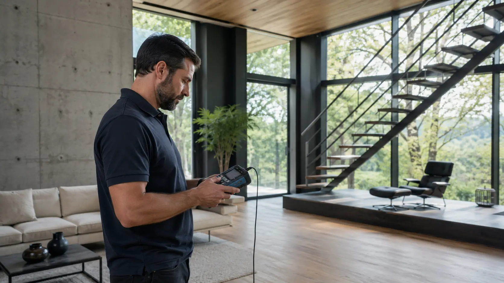
A WiFi site survey measures actual signal strength room by room and floor by floor using a calibrated spectrum analyzer. The output is a heat map of the property showing exactly where dB drops below -67, where reflection patterns create dead spots, and where embedded metal is denser than the architectural plans suggest. Without that map, every hardware decision is a guess dressed up as a recommendation.
Two 6,000-square-foot homes can need completely different access point counts. One may have a wood-frame core with brick exterior; the other may have a reinforced-concrete foundation, low-E glass walls, and radiant floor heating across the primary suite. The first home might need three access points; the second might need six. A site survey (room-by-room signal measurement) is the only reliable way to tell the two apart before quoting equipment.
The map shows where the dead zones are. Next comes putting hardware where it can fix them. Placement decisions follow the survey, not the other way around.
Step 2: Place APs on the Right Side of the Wall
In a concrete-and-glass home, every signal-blocking wall typically requires an access point on each side. AP – access point – is the term enterprise installers use for that device. An AP on one side of a reinforced concrete wall cannot deliver usable signal to a device on the other side, no matter how powerful the radio. The simple rule is one signal-blocking material, one AP on each side if both sides need coverage.
Wired backhaul through ethernet means each AP delivers full speed, with no daisy-chain penalty and no shared-bandwidth math. A 6,000-square-foot single-story home with a poured-concrete foundation typically needs four to six APs; a 4,500-square-foot two-story wood-frame may need only two or three. The difference is the wall material, not the square footage, and that is the part consumer hardware shopping cannot account for. Once the APs sit in the right rooms, the last lever is matching each frequency band to the distance it has to travel.
Step 3: Match the Frequency Band to the Distance
Frequency band selection in a luxury home should follow distance and material density, not router defaults. Reserve 2.4 GHz for penetration-critical zones like garages, far rooms, outdoor terraces, and pool houses. Use 5 GHz for medium-range high-speed zones, and use 6 GHz only where the AP sits in the same room as the device.
Modern enterprise APs handle this allocation automatically once configured for the specific property. The configuration is the operative word: an enterprise AP shipped with factory defaults behaves like a consumer router in a difficult home. Tuning channel widths, transmit power, band steering, and minimum rates is the difference between a working network and an expensive one that still buffers.
With measurement, placement, and frequency working in concert, the home stops fighting the network. That is the right moment to summarize what a homeowner should actually walk away with. From here, the practical questions begin to outnumber the technical ones.
Frequently Asked Questions
Why do I still have dead zones after upgrading my router and adding mesh nodes?
Routers and mesh nodes cannot add signal back; they can only re-transmit what they receive. A mesh node placed behind a concrete or low-E glass wall is itself starved of signal before it talks to any device, so the re-broadcast carries the same weakness forward. The reliable fix is wired backhaul plus correct AP placement, not more wireless re-broadcasters.
How much WiFi signal do concrete, glass and metal actually block – in real numbers?
Reinforced concrete typically attenuates WiFi by 31 dB at 2.4 GHz and 55 dB at 5 GHz. Low-E glass costs another 10 to 25 dB at 2.4 GHz and up to 40 dB at 5 GHz, and unbroken metal surfaces effectively block direct propagation. The comparison table earlier in this article shows the full range per material at both 2.4 GHz and 5 GHz, and a typical signal of -50 dBm dropping 25 dB lands at -75 dBm, which is already in the unreliable-video-call zone.
Is there a way to fix this without rewiring or tearing into the walls?
Partial fixes exist, but they trade convenience for reliability. Powerline adapters and MoCA – Multimedia over Coax – can deliver wired backhaul without new cable runs in some homes, depending on the age of the electrical wiring and the existing coax topology. For most luxury homes, retrofit cable runs are needed in one to three strategic locations, and a skilled installer can usually conceal those runs in existing chases, attics, or crawl spaces.
How does the angle of a wall impact WiFi signal attenuation?
A signal that hits a wall at an angle rather than head-on travels through more effective material thickness, which raises the dB loss. A 45-degree entry angle can nearly double the absorption compared to a perpendicular path. Access point placement therefore considers not only which side of a wall to choose, but the angle at which signals will most often cross it.
Does the moisture content in wood or masonry affect signal strength?
Water absorbs microwave frequencies like 2.4 GHz and 5 GHz very efficiently, so damp wood, fresh concrete, and saturated masonry block signals more than dry materials. Outdoor-to-indoor coverage often degrades during heavy rain or extended high humidity, and freshly poured concrete walls behave worse for the first several months than the same walls after the cure is complete. Plant walls and water features can introduce similar local losses outdoors.
Why does 5 GHz WiFi struggle more with construction materials than 2.4 GHz?
Higher-frequency waves have shorter wavelengths and dissipate energy more easily when they encounter solid barriers. The 5 GHz band offers more bandwidth and faster speeds in clear conditions, but its energy is more easily absorbed and scattered by brick, concrete, and low-E coatings. The same wall that costs a 2.4 GHz signal 5 dB can cost a 5 GHz signal 15 dB or more.
What This Means for the Reader’s Home
Dead zones in a luxury home are an architectural reality, not a router failure. Concrete absorbs the signal, low-E glass reflects it, metal scatters it, and embedded mesh quietly removes a second helping. No hardware purchase from a consumer site can solve a physics problem; only measurement and placement can.
A one-day site survey reveals exactly which walls, windows and floors are costing signal, and where access points need to live. The output is a coverage map and an equipment plan that fits the actual property, not the property as the brochure describes it. That is the difference between a network that survives the next renovation and one that fails again in two years.
At Brilliant Connectivity, every project begins with measuring the property before recommending equipment. In luxury homes, the network is shaped by the building, not the other way around. Starting with a site survey is the cleanest way for any homeowner to have dead zones diagnosed before equipment is chosen.